Press brake tools descriptionDepends of the application and requirements of bends there are various geometry shapes for punches and dies of press brake tooling to perform standard or special sheetmetal bending. Without the connection to the press brake clamping system the type of the tool is important otherwise the required bend is impossible to achieve.
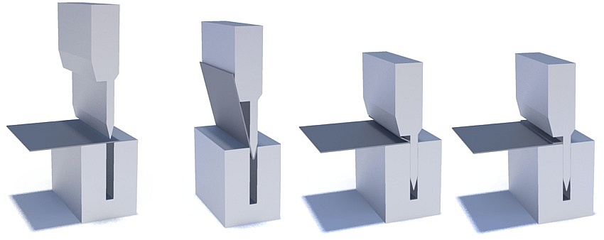
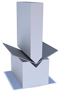
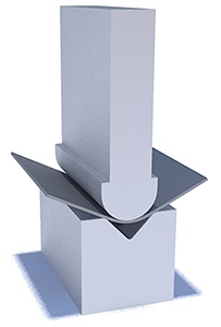
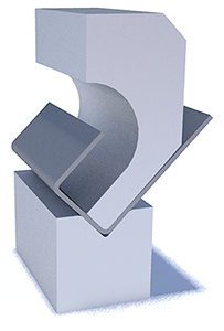
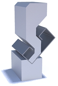
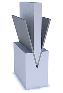
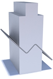
Main terms and glossaryTechnologyAir bending - the technology of the press brake bending where the part contacts with outside edges of the die and with the end of the punch in the middle. The bend is performed by the punch which is moved with the force towards to the center of the die and usually doesn't come with the contact with the die together with the part. In general the V-opening is deeper to compensate the springback of the part after the bending. Air bending is standard and most common technology of sheetmetal bending with the press brake.Bottom bending - the rear principle of bending where the die contacts with the part to move towards to the punch for performing of the bend. The press brake moves the die instead of punch in air bending so the contact with the parts has two points. Bottom bending could be used with rear construction of the machines with movable bottom beam of the press brake or some very special applications. Coining or stamping - the principle of bending which is stamping in reality where the piece has the full contact with the shape of the punch and die when they are connected at the end of bend. This technology allows to get the Z-bend shape of the part, groove, rib or other special deformation. The tools are unique for the part shape and duplicates the shape of the part. Coining or stamping requires the high bending force and could be performed without the necessity of high precision. 3-points bending - special bending technology which is the special for press brakes of Bystronic-Hammerle bending machines. The technology is special because of the construction of the die and the control of the bottom part. The centered bottom position of the die is contacted with the part during the bend and controlled with the CNC. The technology declares as the best for the special and complex parts together with the highest precision of the bending. Machine detailsBending force - declared bending force for the press brake as the max. obtained force for the bend. Bending force is calculated according to the thickness of the part, material and bend requirements.Bending length - declared bending length as the length of the table and the max. possible length for the tooling installation. Bending length usually shows the possibility of length to be bend with the press brake. Bending length could be standard (usually declared) or inside the columns (which the same as the distance between the columns) for the parts which require the deep positioning inside the throat. Moveable beam, trave, traverse - normally top beam of the machine which is moved together with the punch towards to the die to perform the bend. Beam has the controlled move with the hydraulic or electric systems. Stroke of the press brake - declared stroke of the beam to move from the top position. Stroke of the bend together with the details and sizes of the punch and the die are necessary for the study of the bend possibilities. Opening of the press brake, daylight - the max. possible distance from the top position of the beam and the bottom table without the installed tooling. Backgauge of the press brake - backgauge is the main system at the rear part of the pressbrake wich is used as the stopper or fixation of the position of the part during the bending. Backgauge is the complex unit with the separate movements from manual to the servodrived up to 6 moveable axis with CNC control for complex parts and programs. Crowning, deflection - press brake because the construction has the internal structure deflections during the bend which are calculated and the subject for the elimination for the precision of the bend. Depends of the construction of the press brake the compensation of such deflections could be construction integrated, handwheel manual, hydraulic with CNC control etc. Clamping, fixation of the tool - units and systems to clamp punches and dies with the beam and the table of the press brake. There are various systems of the tool clamping and fixation depends of the model and manufacturer, machine possibilities etc. Clamping is connected with the punchholder and die holder units as the middle part of the connection. In general clamping is the manual but could be replaced with pneumatic or hydraulic units. Tool detailsTop tool or punch - top tool which is connected to the top beam of the press brake.Die - bottom tool which is connected to the bottom table. Punchholder - top clamping unit with the fixation elements and intermediate elements to hold the punch inside the unit. Die holder - bottom clamping tool with fixation elements to hold the die on the table. Angle of the tool - angle of the punch tip or die groove as desired with the tool geometry. Radius of tool - radius of punch tip at the end or external radius of the die (two external points of the die) or the internal radius of the die (internal radius inside the groove of the die). Groove of the die - internal groove of the die (V-opening) as the detail of the bottom tool. Multi-V dies - special dies with the several V-openings on different sides for the universal use. T-shape dies - T-dies as the 1-V dies with the different heights. Height and width of the tool - external sizes of the tools. Additional
Attention: All the brands, machines, manufacturers and trademarks are used only for the information, are not connected with PRECITOOLS and are property of their respected owners. |